Switching contacts
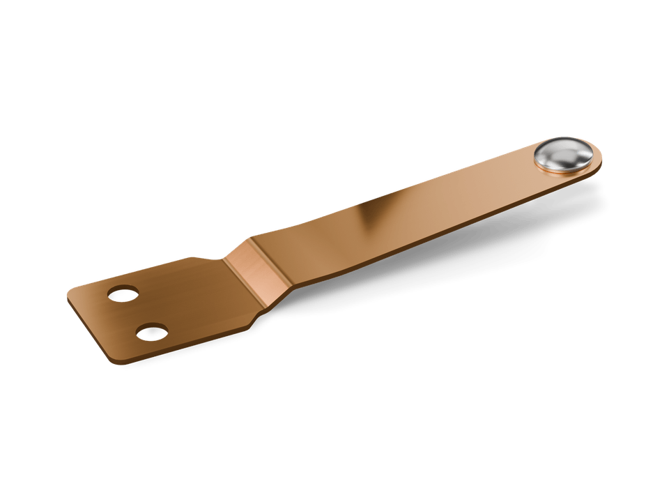
Contact parts with riveted or welded contacts
Switching contacts
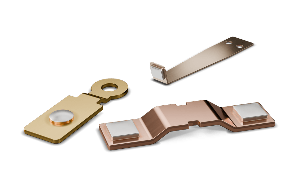
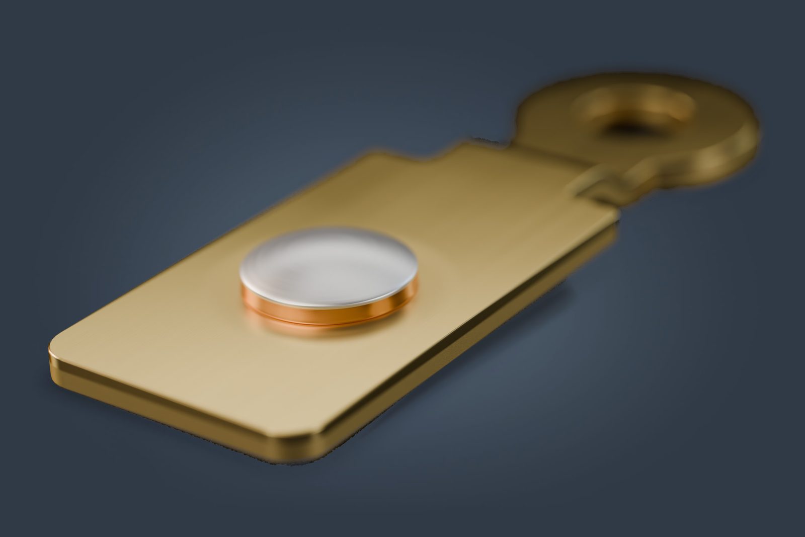
Contact springs with riveted or welded contacts, contact bridges and contact carriers from a single source. ACA Atlas Contacte in Wehr (Baden), Germany, resistance-welds contacts inline in the stamping process and rivets contacts in-house.
01 Overview
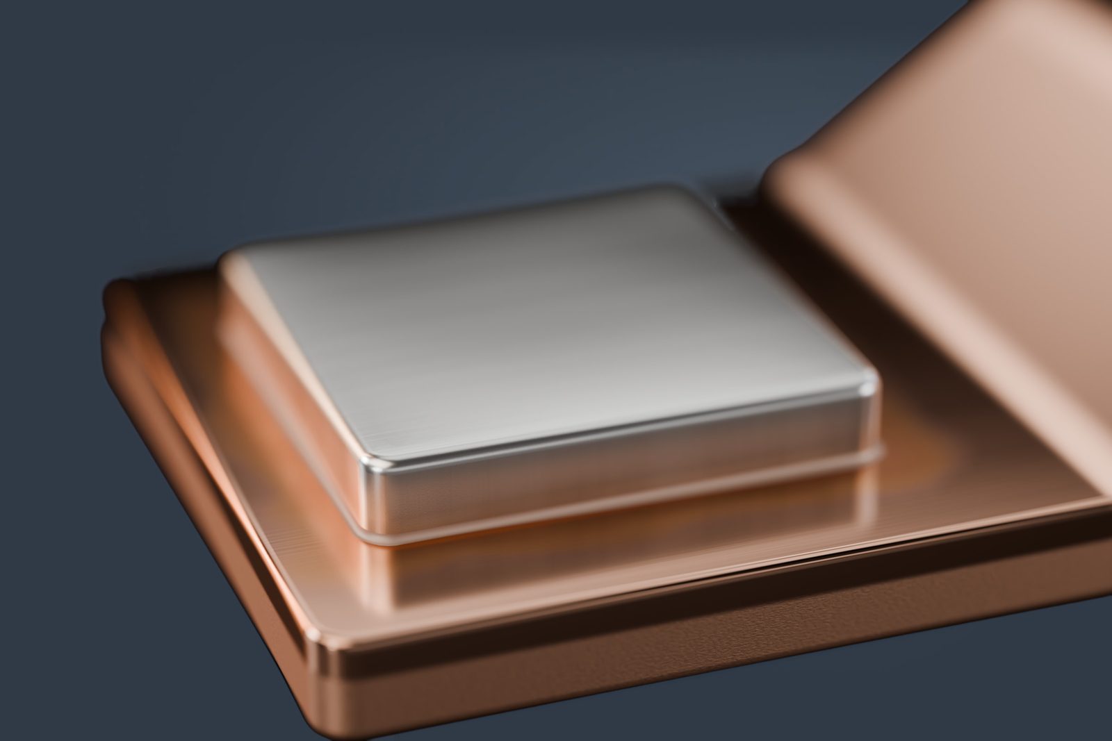
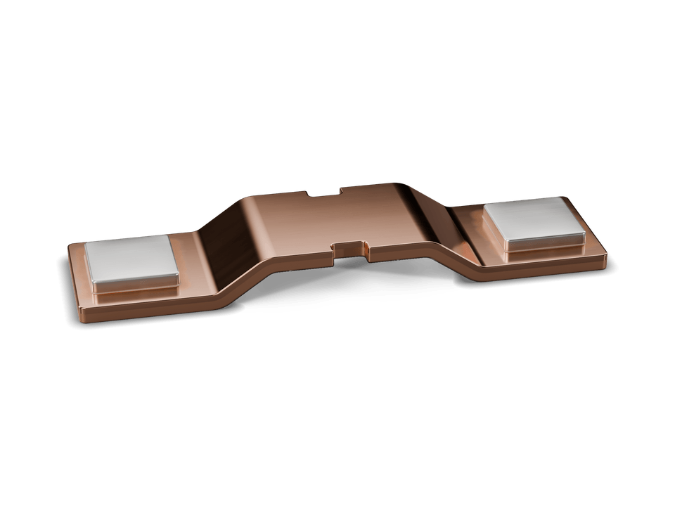
A contact part with a riveted or welded contact consists of two components: a stamped carrier and a contact tip made of a different material. Typical examples are switching contacts such as contact bridges and contact carriers. If they come from different suppliers, tolerances add up, parts travel between plants, and when something goes wrong each supplier points to the other.
At ACA Atlas Contacte the part stays in-house from stamping to joining. We stamp and form the carrier in our own progressive die. Contacts are resistance-welded inline, that is within the stamping process itself, while the part is still attached to the carrier strip. Riveting also takes place at our plant in Wehr, on a separate riveting station rather than in the progressive die. Contact welding is part of the scope of our ISO 9001:2015 certificate.
The joining processes as a service, inline resistance welding and riveting, are described on contact welding and riveting.
02 Inline welding
The first stations cut the carrier contour. Pilots engage pilot holes in the carrier strip and fix the position of every subsequent weld.
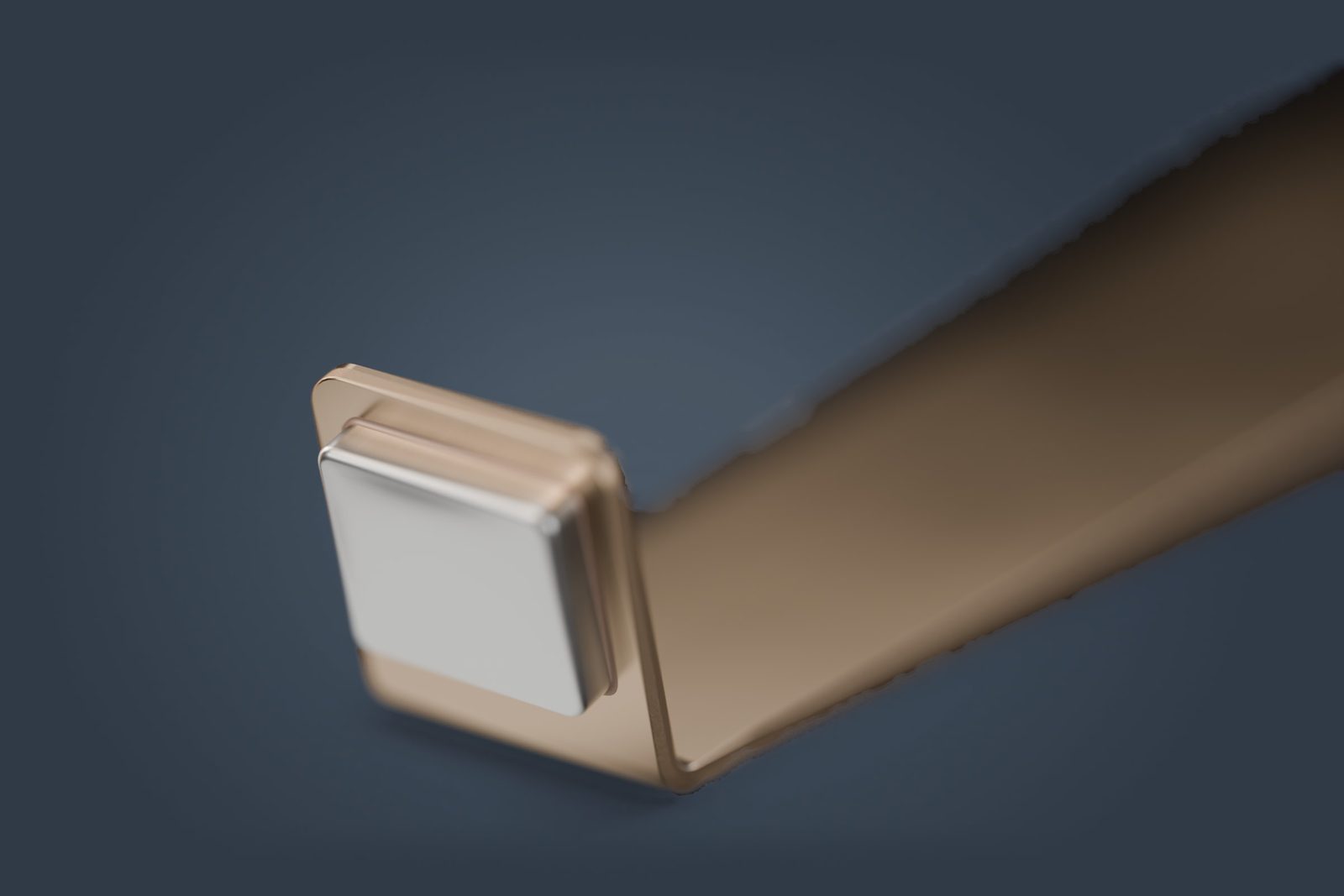
At the welding station the contact material is placed precisely on the intended spot of the carrier.
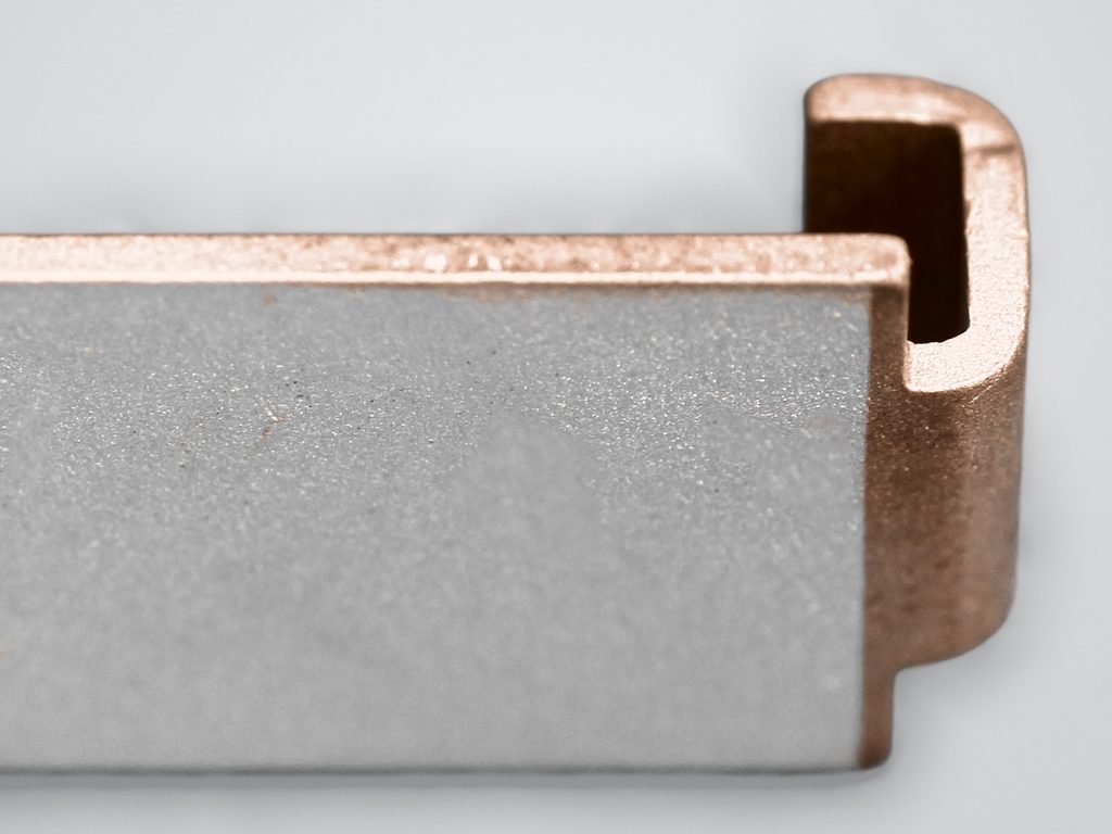
Electrodes press contact and carrier together, and a short current pulse heats the interface. The result is a metallurgical bond, with the heat confined to a small area.
Bending and forming usually follow welding, so that the joint is made on flat strip.
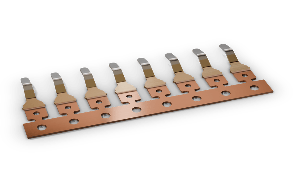
The tipped part is separated or stays on the carrier strip for automatic downstream processing.
03 Riveting
For riveting, the carrier is pierced. At ACA Atlas Contacte, riveting runs on a separate riveting station. The contact rivet is inserted and its shank is formed into a closing head on the back. The joint holds by form and force fit, without heat input. That makes riveting independent of whether contact and carrier material can be welded.
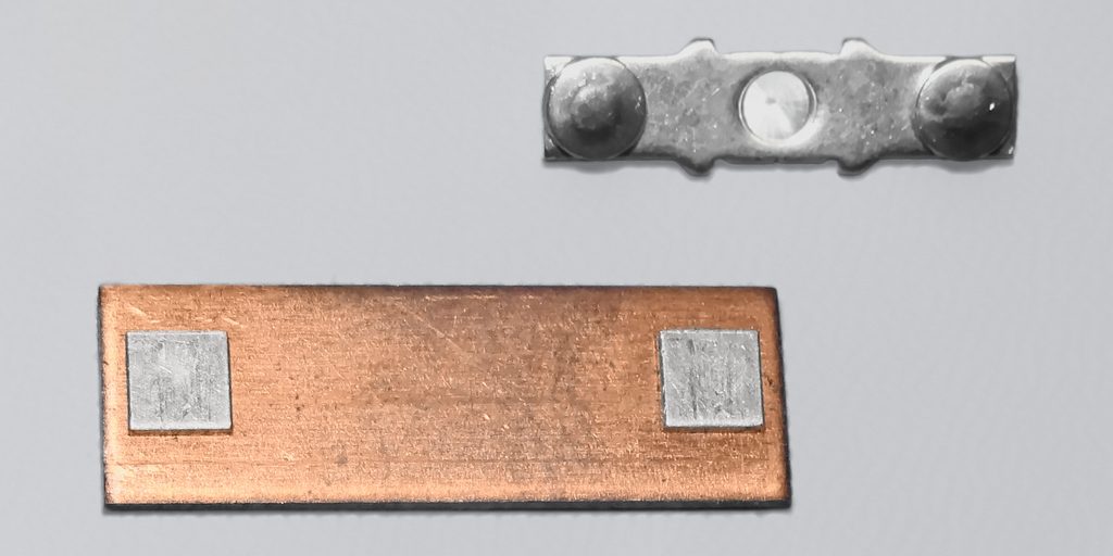
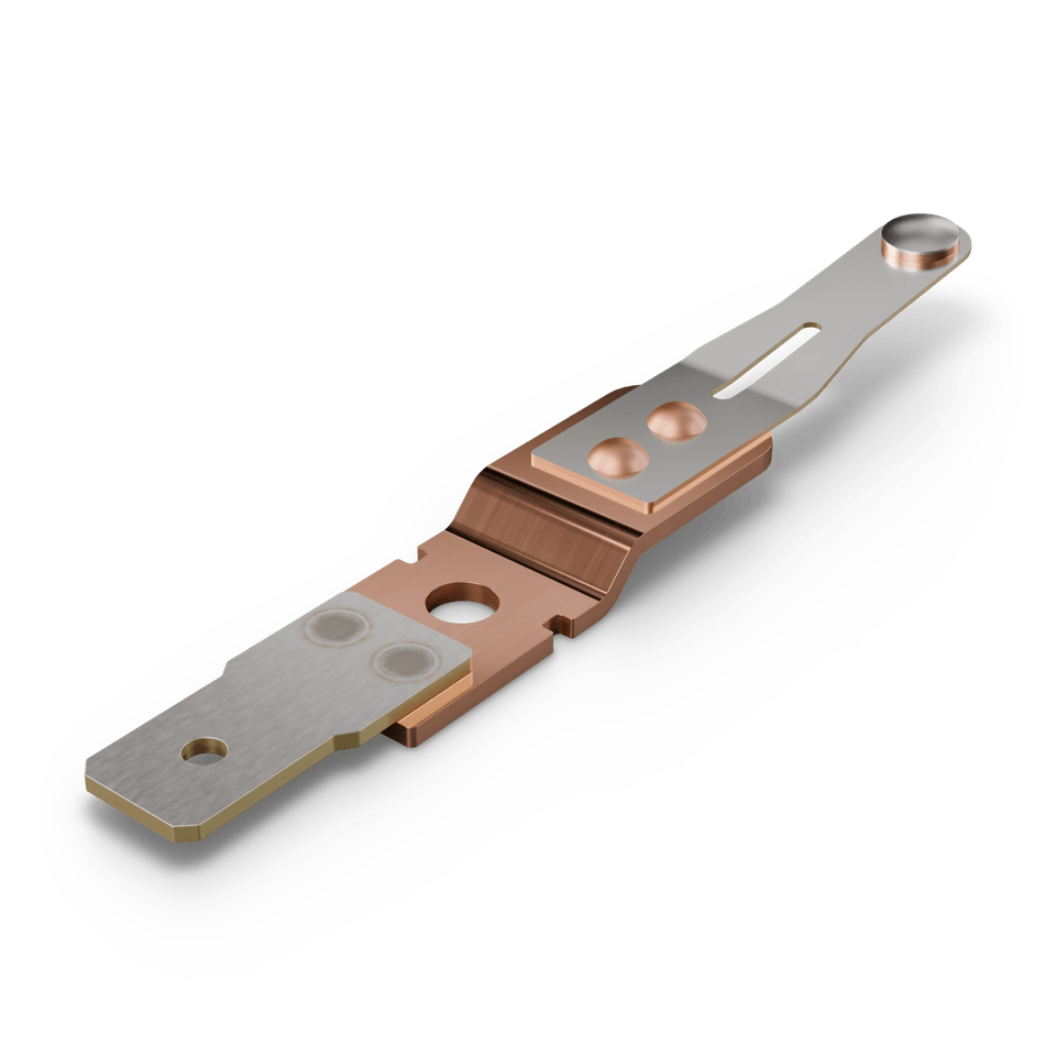
Our own high-current contact band shows that we rivet in series: individual contact pieces of high-conductivity copper are riveted onto a resilient carrier band of stainless spring steel.
04 Choosing a process
A welded contact needs no hole in the carrier and leaves the back flat, but the material pairing must be weldable. A riveted contact holds by form and force fit without heat input and is largely independent of weldability.
05 Design
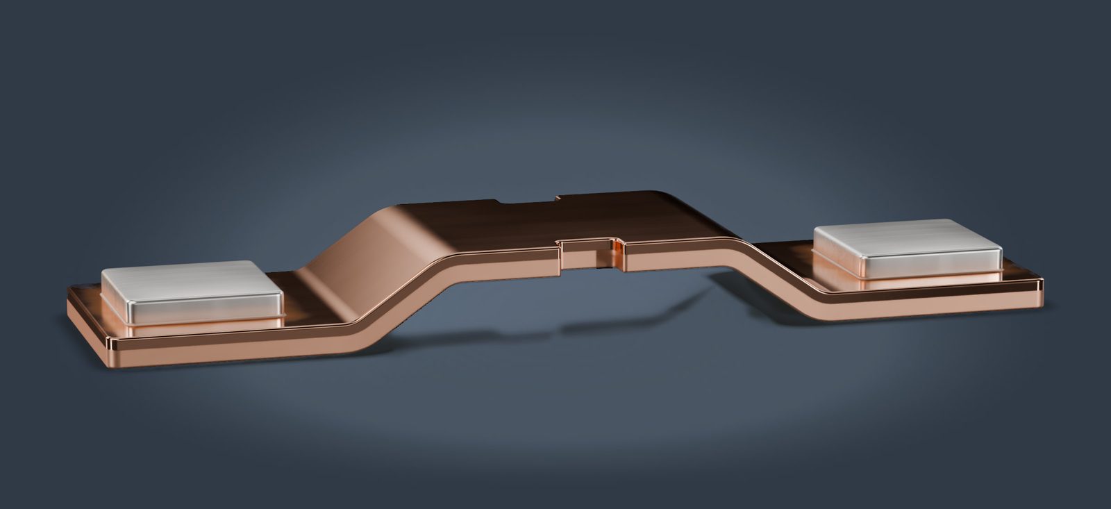
Reference the position and height of the contact tip to the functional surfaces of the carrier, such as the mounting hole, not to its outer contour.
Joints belong on flat areas, away from bend zones. Bends close to the joint can distort the contact tip.
On tipped contact springs, the joint sits outside the highly stressed spring area so that spring force and characteristic are preserved.
Whether the carrier is plated before or after joining affects weldability and the contact surface. We agree the sequence with you and our plating partner.
Position, height and secure fixing of the contact tip are agreed with you as inspection characteristics for samples and series.
06 Technical data
| Property | Value |
|---|---|
| Parts | Tipped contact springs, contact bridges, contact carriers, riveted or welded assemblies |
| Welding process | Resistance welding, inline in the stamping process |
| Riveting | in-house, on a separate riveting station |
| Alternative without joining | Stamped parts from clad strip, a two-layer contact material (bimetal) |
| Contact material | to your specification |
| Carrier materials | Copper alloys, steel, stainless steel to your specification |
| Contact tip dimensions | on request |
| Delivery forms | loose, on carrier strip (reeled), taped |
| Quality management | ISO 9001:2015 (DQS), scope including contact welding |
Dimensions of contact tip and carrier are given per project on request.
Last updated:
FAQ
A tipped contact spring is a contact spring with a contact of a different material, usually silver-based, riveted or welded onto it. The spring provides the contact force, the tip the contact surface. Springs without a tip are covered under contact springs.
We weld contacts inline, that is within the stamping process, while the part is attached to the carrier strip. Riveting is also done in-house, but as a separate operation on a separate riveting station. We define the sequence for each part.
We use resistance welding. Current and electrode force create the joint directly at the interface, inline in the stamping process.
Yes. Contact bridges with two contact tips are among our typical parts. Number and position follow your drawing.
You specify the contact rivets and contact material. Whether we source them or you supply them is agreed in the quotation.
Contact parts with riveted or welded contacts
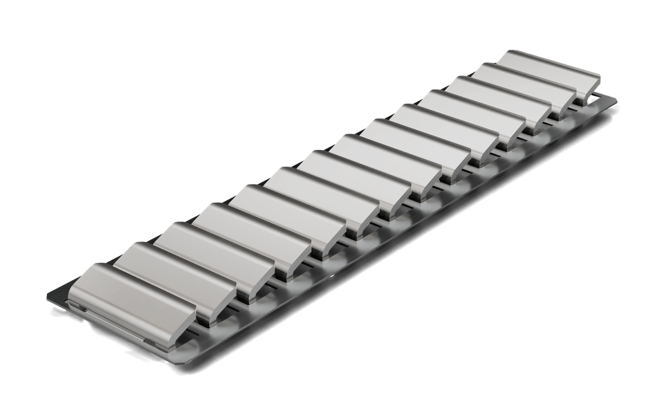
Stainless spring steel carrier with riveted contact pieces of silver-plated copper
Clamping, grounding, basket, push-button and retaining springs
Riveted and welded assemblies
Resistance welding and riveting in-house
Single and multi-component strips, selectively plated on request
Request a quote
Send us the drawing with contact material, carrier material and quantities. We will reply with a recommendation for riveting or welding and a quote.