01
Design for stamping: costs are decided on the drawing
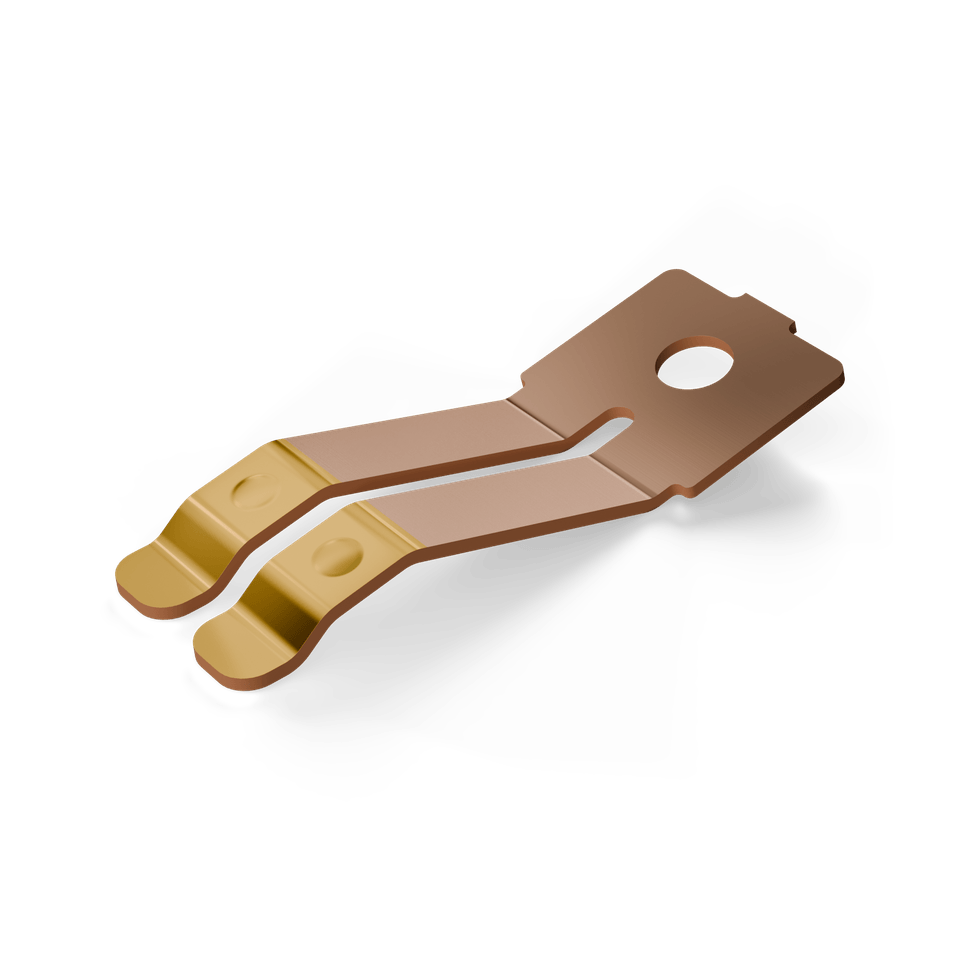
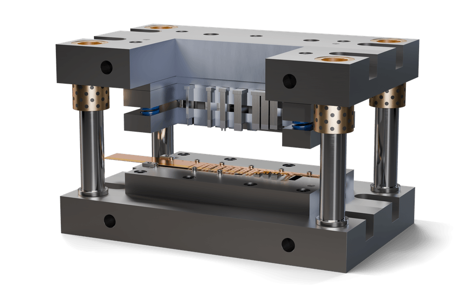
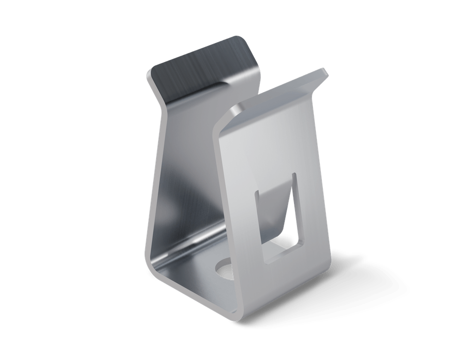
A stamped and bent part is a component that is cut and formed from metal strip, in volume production usually in a progressive die or on a stamping and bending machine. Tooling effort, unit price and process reliability depend almost entirely on the geometry shown on the drawing. A tolerance that is too tight, a hole too close to a bend or a bend parallel to the rolling direction can mean an extra die station, rework or scrap.
The following rules are rules of thumb that match our production practice in Wehr. They apply to common materials and thicknesses of contact and spring parts and do not replace a check of the individual part. What is feasible for your part depends on material, temper, geometry and quantity. So talk to us early, ideally before the drawing is released. A short discussion at the concept stage often saves more than any later optimisation.
02
Rules of thumb at a glance
| Criterion | Rule of thumb (t = sheet thickness) | Reason |
|---|---|---|
| Inside bend radius | about 1 × t, smaller for soft materials, 2 × t or more for spring tempers | Radii that are too small crack on the outside of the bend. The material datasheet gives limits per temper and rolling direction. |
| Hole diameter | at least 1 × t, for stainless steel and spring-temper materials rather 1.5 × t | Slender punches buckle or break and wear faster. |
| Web width and edge distance | at least 1 × t, preferably 1.5 × t | Narrow webs distort during cutting and tear during bending. |
| Hole-to-bend distance | at least 2 × t plus inside bend radius | Closer holes are distorted by the bend. |
| Flange length | at least 2 to 3 × t plus inside bend radius | Flanges that are too short cannot be guided and bent reliably. |
| Slot width | at least 1 × t, more for hard materials | Narrow slots need thin punches that break easily. |
| Bend relief | width at least 1 × t, depth at least inside bend radius plus t | Prevents tearing where a bend line meets an outer edge. |
Rules of thumb for orientation at the concept stage, not guaranteed manufacturing limits. We give binding values for your part after reviewing the drawing.
Hole, web and edge distance
Rule of thumb
Hole diameter d at least 1 × t, for stainless steel and spring-temper materials rather 1.5 × t. Web width and edge distance b at least 1 × t, preferably 1.5 × t.
Hole-to-bend distance
Rule of thumb
Distance a at least 2 × t plus the inside bend radius r. A hole any closer is distorted during bending.
Flange length and slot width
Rule of thumb
Flange length l at least 2 to 3 × t plus r. Slot width w at least 1 × t, more for hard materials.
Bend relief
Rule of thumb
Width at least 1 × t, depth at least r plus t. Prevents tearing where a bend line meets an outer edge.
03
Bend radius, rolling direction and springback
In bending, the outside is stretched and the inside compressed. If the inside radius is too small, the outer fibre cracks. The permissible minimum radius is usually given as the ratio of radius to thickness and depends on the temper: the harder and springier the temper, the larger the radius must be.
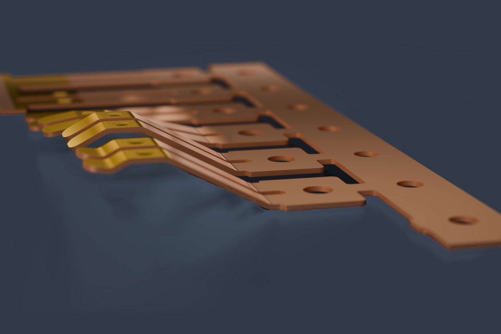
Rolled strip has a grain direction. Bend lines across the rolling direction tolerate much smaller radii than bend lines parallel to it. If a part has bends in both directions, it is often placed at an angle in the strip, or the critical direction receives a larger radius. Mark on the drawing which bend is critical to function. We will then align the strip layout accordingly.
After bending, every part springs back slightly. Spring-temper materials and large radii spring back more than soft materials and small radii. The tool compensates for springback by overbending. Tight angle tolerances are possible but need fine-tuning in the tool.
Inside radius about 1 × t
Rule of thumb
Rule of thumb for common contact and spring materials. Soft materials also allow smaller radii.
Radius too small
Avoid
The stretched outer fibre cracks.
Spring temper: 2 × t or more
Rule of thumb
The harder and springier the temper, the larger the radius has to be.
Springback
The tool bends beyond the target angle. Once released, the part springs back to the target angle.
Bend line across the rolling direction
Recommended
Tolerates much smaller bend radii.
Bend line parallel to the rolling direction
Needs a larger radius, otherwise the outside of the bend may crack.
Bends in both directions
The part is often placed at an angle in the strip, or the critical direction gets a larger radius.
04
Holes, webs and slots
Holes and cut-outs are cut with a punch and a die plate. The punch cannot be made arbitrarily slender, otherwise it buckles or breaks. That is where the rules of thumb for minimum diameter and slot width come from. Narrow webs between two cut-outs, or between a cut-out and the outer edge, distort during cutting and can tear during bending.
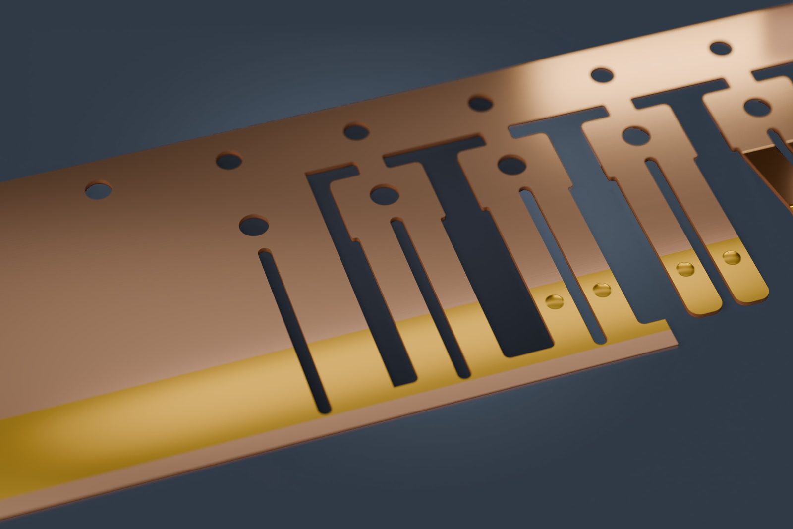
If a hole is too close to a bend line, the bend pulls it oval. If the distance cannot be increased, the hole can be pierced after bending, which usually costs an additional die station. For springs there is a further point: holes, notches and sharp inside corners act as stress raisers in the highly stressed spring zone.
- Add radii to inside corners rather than leaving them sharp
- Dimension hole patterns from common datums
- Keep cut-outs out of the highly stressed spring zone
05
Burr, burr side and cut edge
Every stamped edge has a typical cut surface: a rollover on the side where the punch enters, a smooth burnish zone, a rough fracture zone and, on the exit side, a burr. How high the burr is depends on the cutting clearance, the material and the wear condition of the tool.
The burr side belongs on the drawing. It matters for contact faces, sliding faces, locating faces and safe handling. For bending the rule of thumb is: burr on the inside of the bend wherever possible, because otherwise the stretched outside can crack from the fracture zone. Where a burr is a problem, deburring, coining the edge or reversing the cutting direction can help. Each of these is an additional process step.
Zones of the cut edge
1 rollover on the punch side, 2 burnish, 3 fracture zone, 4 burr on the exit side.
Burr on the inside of the bend
Recommended
The stretched outside stays clear of the fracture edge.
Burr on the outside of the bend
Avoid
The stretched outside may crack from the fracture zone.
06
Tolerances: as tight as necessary
Tolerances are among the biggest cost drivers for stamped and bent parts. Cut dimensions produced in a single die station can be held very accurately because the tool reproduces them directly. Dimensions across a bend vary more, because sheet thickness, strength and springback come into play. Dimensions that add up across several bends vary the most.
For untoleranced dimensions, drawings usually refer to a general tolerance standard such as ISO 2768-m. For stamped steel parts, DIN 6930-2 is a dedicated general tolerance standard that takes the specifics of stamping into account. Specify tight tolerances only on functional dimensions, and reference them to the faces on which the part will later locate or make contact.
A common mistake is chain dimensioning across several bends. It is better to dimension from a common datum that is easy to measure on the part. We will tell you which tolerances we can commit to for your part after reviewing the drawing.
Scatter by type of dimension
Cut dimensions from one die station scatter least, dimensions across one bend more, dimensions across several bends most.
Chain dimensioning across several bends
Avoid
The deviations add up from one dimension to the next.
Dimensioning from a common datum
Recommended
Every functional dimension refers to a face that is easy to measure on the part.
07
Carrier strip and strip layout
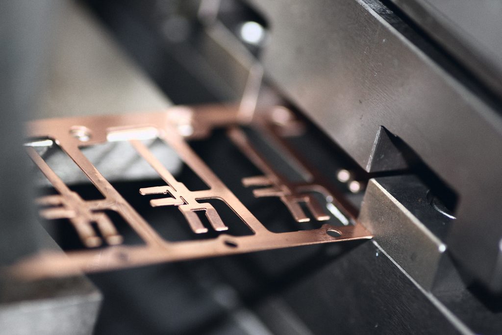
In a progressive die, the part stays connected to the carrier strip until the last station. The strip carries it from station to station. Pilot pins engage pilot holes in the carrier and locate the strip precisely in each station, and the feed equals the pitch in the strip.
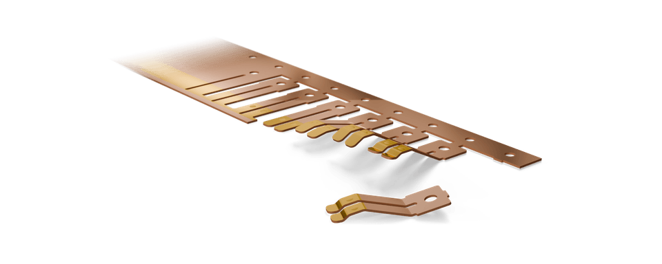
Three points matter for the design. First, the attachment: where the part is joined to the carrier, a small cut-off stub remains. It should not sit on a contact or sealing face. Second, the position in the strip, which decides rolling direction, material utilisation and bending sequence. Third, the delivery form: if the parts are to be supplied on reels and processed automatically, we agree pitch, carrier width, pilot holes and winding direction with you.
- Single-sided carrier: compact, good for flat parts
- Double-sided carrier: stable transport for long or delicate parts
- Supplied on reel, on tape, in magazines or loose in bulk
Single-sided carrier
Compact, good for flat parts.
Double-sided carrier
Stable transport for long or delicate parts.
08
Notes on plated parts
With plated parts, the sequence of stamping, bending and plating determines the result. Pre-plated strip is economical but leaves unplated cut edges. If plating takes place after stamping, the edges are protected too, and functional zones can be plated selectively, for example gold on the contact zone and tin on the solder termination.
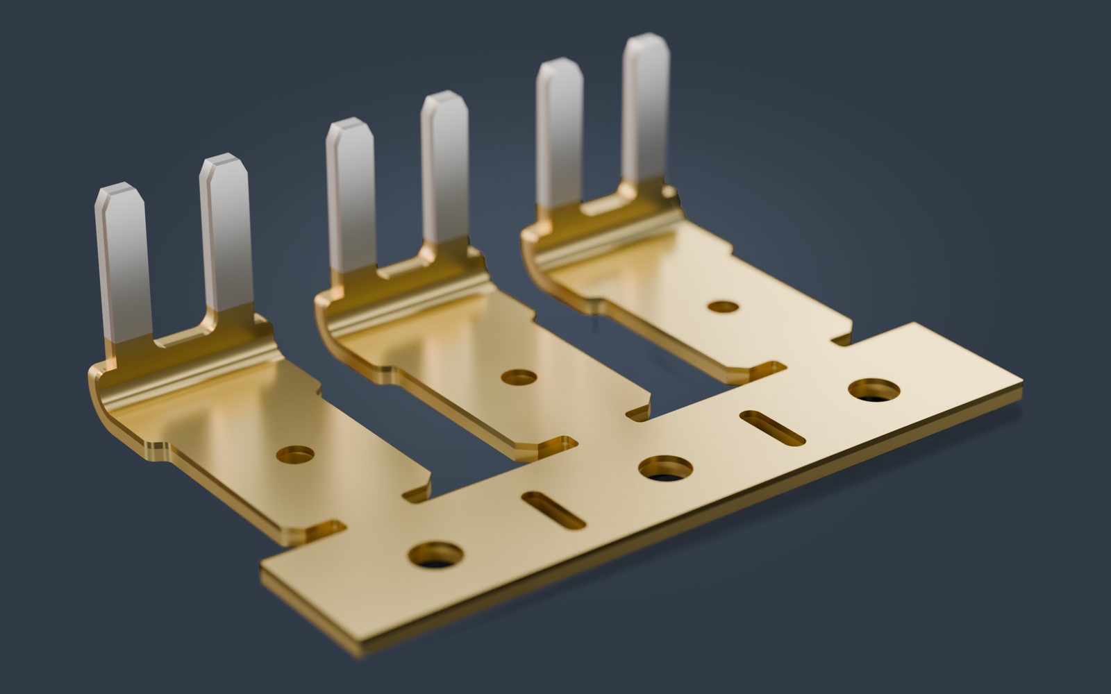
More on layer systems in our guide to materials and finishes and on the surface finishes page.
- Include layer thicknesses in the tolerance chain, especially for press-fit zones and tight mating dimensions
- Hard, brittle layers such as nickel or hard gold only tolerate larger radii when bent after plating
- State functional zones, layer system and minimum thicknesses clearly on the drawing
- For high-strength steels, consider the risk of hydrogen embrittlement in electroplating
Pre-plated strip
Economical in high volumes. The cut edges stay unplated.
Plated after stamping
The edges are plated too, and selective zones are possible.
Selective plating
For example gold on the contact zone and tin on the solder tail.
09
What to include in your enquiry
-
Material and temper
Material designation with temper and sheet thickness, and for springs the required force-travel characteristic.
-
Finish
Layer system, thicknesses and functional zones, and whether plating may take place before or after stamping.
-
Functional dimensions
Functional dimensions with tolerance and datum, burr side and critical bends marked, everything else to general tolerance.
-
Quantity and delivery form
Annual demand, batch size and the delivery form you need: on reel, on tape, in magazines or loose in bulk.
-
Data
Drawing as PDF and 3D model, for example as a STEP file. For an existing tool, any information about it is welcome.
-
Inspection requirements
Special inspection characteristics, first article inspection and the documentation you expect.
10
How we support your design
-
Consulting
We check your drawing or concept for manufacturability and suggest changes that make the tool and the unit price more economical.
-
Design
If you wish, we design the part with you and define strip layout, carrier strip and bending sequence.
-
Tool making
The tool is built in our own tool shop in Wehr. Changes are made there without detours.
-
Samples and prototypes
Samples show whether function and tolerances are right before series production starts.
-
Small batches and series production
From small batches to high-volume production, in a progressive die or on stamping and bending machines.